
Anyone who has bought the educational edition of the Lego Mindstorm EV3 would notice one glaring omission; It doesn’t come with a charger for the included rechargeable battery!
Unlike many common lithium ion devices, the EV3 is not capable of charging via USB, and must use a separate charger. The official Lego charger is expensive and charges only a single battery at a time; quite a pain when you have 10 depleted batteries to charge after a class. There is a third party multi-charger that can charge 8 batteries at a time, but it is even more expensive than buying 8 official chargers!
Thankfully, building your own charger is relatively simple. The actual charging circuit is within the battery itself, and it uses a Monolithic Power MP26123 IC that can accepts between 9 to 24V.
The official Lego charger is simply an AC to DC power supply that supplies 10V and up to 700mA. Power supplies capable of supplying more current are OK; the battery will only draw as much as it needs. Power supplies providing higher voltages will probably be fine up to 24V, but I won’t go beyond 12V; it’s unnecessary and there’s no guarantee that every EV3 battery uses the same charging IC or that all the components are rated to 24V.
I’ll be sharing designs for both a 2-batteries charger as well as a 10-batteries charger.
Two Batteries Charger
Parts List
- 10V 2A power supply (USD$3.51 or search)
- 3.5 mm x 1.35 mm barrel plug (USD$1.09 for pack of 10 or search)
- (Optional) 2 core wires
- (Optional) Heat shrink tubing or electrical tape
If you have difficulties sourcing for a 10V power supply, you can use a 12V instead. If you’re planning to modify the design to charge more than 2 batteries at a time, get a power supply with a higher current limit. You should cater at least 700mA per battery.
Tools
- Soldering iron
- Solder
- Wire cutter, scissors, pen knife, or your teeth (…not recommended)
- (Optional) Multi-meter
Procedure
Step 1: The power supply will come with a barrel plug, but it’s probably not the right size for the EV3 battery. Cut it off near the plug (…but leave a bit of wire so that you can reuse it for a future project).
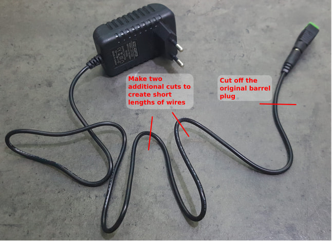
Step 2: You’ll need two short length of 2 core wires to connect the 3.5mm barrel plug to the power supply. If you do not have any extra wires, cut two short length of wires from the power supply.
Step 3: Strip a short length of insulator from the wires (…about 2-3 mm would be enough), and solder it on to the 3.5mm barrel plug. It shouldn’t matter at this point, but take note of which wire was soldered on to the positive terminal and which was soldered to the negative. Using a pair of pliers, bend the claw on the negative terminal to grip on to the wires. Finally, attach on the plug cover. Do this for both the barrel plugs.
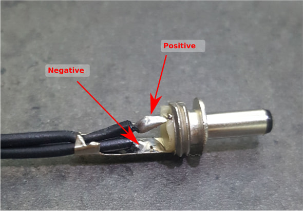
Step 4: Solder the other end of the wire to the power supply. If you have a multi-meter, check the polarity of the wires on the power supply before soldering to ensure that the positive wires on the power supply gets connected to the positive terminal on the barrel plug. If you don’t have a multi-meter, you can check the wire colors (…red is positive) or the connection on the original barrel plug (…inner conductor is positive). Use heat shrink tubing or electrical tape to insulate the positive and negative wires from each other.
That’s it! You’re done. If you don’t want to cut off the original barrel plug on the power supply, you can also make use of the adapter (…you can see it attached to the barrel plug in the first photo) to connect the wires. This adapter often comes free with the power supply, or you can buy it separately for less than a dollar.
Ten Batteries Charger
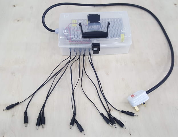
You can build a 10 batteries charger in the same way as the 2 batteries charger; just get a power supply capable of higher current (…at least 7A). But I personally haven’t had the best experience with cheap high current power supply that are fully sealed in a plastic casing. Many have failed on me, and a teardown of these power supplies suggests that they are not capable of handling the current that their sellers claims. Instead, we’ll be using an open power supply. These have metal casings with ventilation openings, and are much more capable of dissipating the waste heat from high current operations.
WARNING! These power supplies have exposed conductors connected to the mains, and can result in death or serious injuries if improperly handled. It may be illegal in your country to perform mains wiring without appropriate qualifications.
Parts List
- 12V 10A power supply (USD$12.78 or search)
- 3.5 mm x 1.35 mm barrel plug (USD$1.09 for pack of 10 or search)
- 2 core wires (20AWG or thicker)
- 12V 40mm cooling fan (USD$0.94 or search)
- (Optional) 40mm fan filter (USD$1.04 for 5 or search)
- Mains plug (depends on your country)
- Mains cable (…3 conductors, with a suitable voltage rating)
- Plastic box (…hold the power supply)
- (Optional) Cable gland
- Terminal block (…recommend to get those with wire protection leafs ) (USD$1.20)
- (Optional) M3 screws (…for securing power supply)
- (Optional) M4 screws and nuts (…length depends on the fan)
For the power supply, we’re getting a 12V as 10V power supplies are less common (…we’ll adjust it later to reduce the voltage).
Tools
- Soldering iron
- Solder
- Drill
- Screw driver
- (Optional) Hot glue gun
- Wire cutter, scissors, pen knife, or your teeth (…not recommended)
Procedures
Step 1: Strip a short length of insulator from the wires (…about 2-3 mm would be enough), and solder it on to the 3.5mm barrel plug. It shouldn’t matter at this point, but take note of which wire was soldered on to the positive terminal and which was soldered to the negative. Using a pair of pliers, bend the claw on the negative terminal to grip on to the wires. Finally, attach on the plug cover. Do this for all of the barrel plugs.

Step 2: We’ll need to cut a few holes in the plastic box
- Screw holes for securing the power supply: There are screw holes in the bottom of the power supply, and we’ll be using them to secure the power supply in the plastic box. Place the power supply in the plastic box, mark out the position of the holes, then drill the holes with a 3mm drill bit. Alternative: You can also hot glue the power supply into the box, but if doing so, leave it for after all the wiring are done.
- Hole for the cable gland: The cable gland hole size will depend on your cable gland, which in turns depends on your mains cable; mine is 15mm and was cut with a Forstner bit. If you don’t have a suitable drill bit, you can use a Dremel, or drill multiple holes close to each other and cut out the excess using a wire cutter.
- Holes for the 2 core cables: The hole size will depend on your wire, and is probably around 3 to 4mm. You’ll need 10 of these holes.
- Hole for the cooling fan: You’ll need a 40mm hole for the ventilation, and can cut it using a Forstner or Spade bit. If you don’t have a suitable drill bit, you can use a Dremel, or drill multiple smaller holes. You may also need 4 holes to screw on the fan. Alternative: You can also hot glue the fan on to the box.
- Ventilation holes: You can’t just have an air inlet without an outlet. Drill a few holes to allow the air to escape / enter the box. Don’t position it too close to the fan, else there won’t be much air circulation in the box.
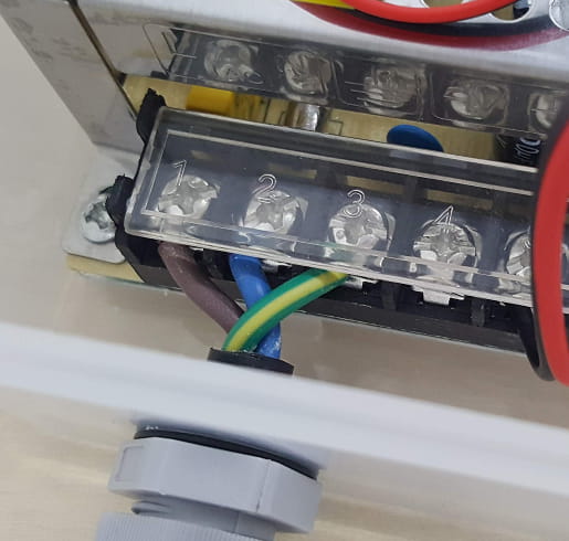
Step 3: Pass the mains cable through the cable gland, then connect one end of the mains cable to the power supply, and the other end to the mains plug. Brown is for Live, Blue for Neutral, Yellow/Green for Earth.

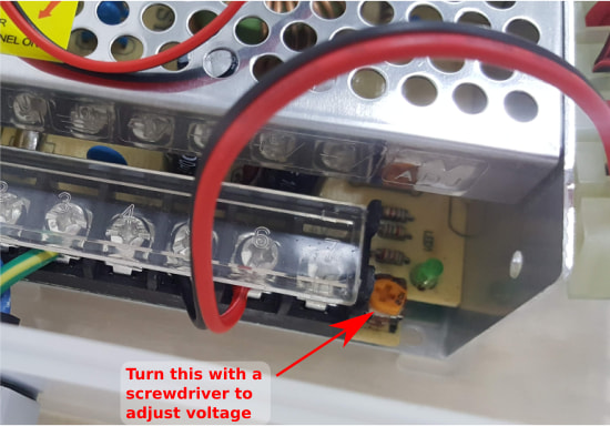
Step 4: Most power supply will come with a rheostat that can be used to adjust the voltage within a limited range. Since we don’t need 12V, we’ll adjust the voltage down a little to as close to 10V as we can get. Plug in the mains plug and turn on the power. The power supply is now live, so be careful not to come in contact with any live terminals. Measure the output voltage with a multi-meter, and use the screwdriver on the rheostat to adjust the voltage. If you’re not confident of doing this safely, just skip this step. The EV3 will charge just fine from 12V.
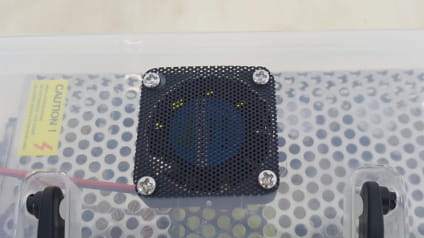
Step 4: The fan is equipped with a connector at the end of its power cable. We won’t need that, so cut it off and strip off 4 to 5mm of insulator. Attach the fan and fan filter on to the plastic box. You can use M4 screws for this or simply hot glue the fan on.
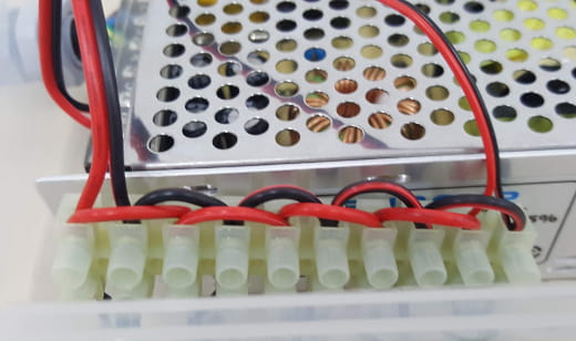
Step 5: Wire the output of the power supply to the terminal block. Use short wires as jumpers to connect all the positives together and all the negatives together. Connect the positive on the terminal block to the positive of the barrel plug, and repeat the same for the negative. Connect the wires on the fan to the terminal as well. The red wire on the fan should go to positive.
Step 6: Secure the power supply in the box using the screws or hot glue. Pull any excess wires out of the box, then tighten the cable gland. If not using cable gland, apply hot glue to ensure that the mains cable won’t get pulled out easily.
That’s it! If you have a multi-meter, you may want to check all the barrel plugs to make sure that the voltages and polarities are correct (…inner positive, outer negative).